
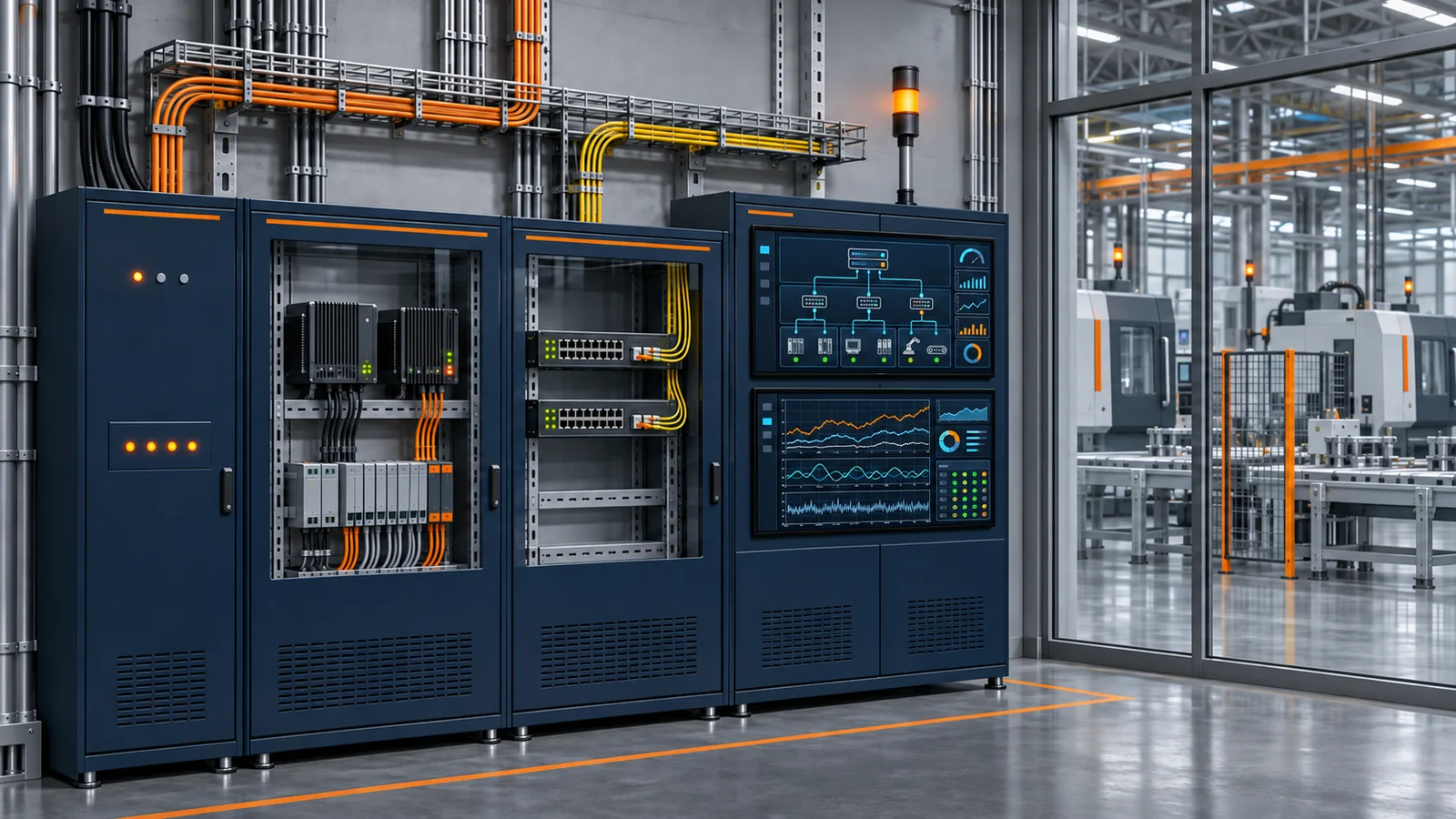
Machine Data Acquisition and Production-Line Connectivity
Capture data from mixed-vendor equipment accurately and reliably before reusing it for monitoring, traceability, and analysis
Built around multi-protocol acquisition, a data hub, and SCADA, the system standardizes equipment tag lists, states, alarms, and historical data to provide a consistent data entry point for MES, OEE, SPC, and energy analysis. Legacy equipment and special protocols require prior assessment. Edge computing and AI diagnostics are not presented as default capabilities.
Good fit
Best-Fit Scenarios
- • Production workshops with mixed-vendor equipment that need consistent tag lists, states, and alarm definitions.
- • Standalone machines or legacy lines that need monitoring and data services while retaining existing control logic.
- • Factories where multiple upper-level applications repeatedly acquire the same equipment data and a unified data hub is planned.
- • Projects with explicit acceptance requirements for communication interruptions, backfill, alarm archives, or interface auditing.
Scenarios Requiring Separate Assessment
- • Projects unwilling to provide equipment documentation, test windows, or network conditions while requiring a guarantee that every machine can be connected.
- • Requirements to bypass OEM security mechanisms, modify control programs without authorization, or defeat existing safety interlocks.
- • Expectations that data connectivity is equivalent to a turnkey scope covering complete MES, MOM, digital twins, or AI predictive maintenance.
- • High-frequency synchronized control or hard real-time safety control that a general acquisition platform or cloud service would be expected to perform directly.
Lean manufacturing context
Core capabilities
Mixed-Vendor Protocol Connectivity
Connect PLCs, CNCs, robots, instruments, and test equipment using verified protocols and device types. Equipment without communication ports, with proprietary protocols, or lacking documentation undergoes technical verification first.
Unified Tag Lists and Data Semantics
Manage equipment hierarchies, tag names, data types, units, ranges, read/write properties, and quality codes to provide upper-level applications with a consistent data dictionary.
Real-Time SCADA Monitoring
Build equipment-state, parameter, trend, and operating screens around process flows. Multi-vendor configuration platforms or custom supervisory-software approaches are selected by scenario without locking the solution to one brand.
Alarm Prioritization and Event Governance
Configure alarm levels, trigger and reset conditions, acknowledgement, archiving, and notifications, using debounce and suppression rules to distinguish notifications, process abnormalities, and faults requiring action.
Historical Data and Trend Analysis
Select real-time, relational, or file-based storage according to data frequency and use, providing trends, time-range filtering, and event association. Retention policies and sampling capabilities are designed by project.
Reconnection and Offline Data Backfill
Provide session management, automatic reconnection, and heartbeat monitoring. Where the data source or edge layer can buffer data, configure resumable backfill and verify the order and completeness of recovered records.
Reusable Data Services
Provide equipment data to MES, OEE, SPC, and energy applications through standard APIs, messaging, or database interfaces, reducing repeated direct connections from multiple systems to shop-floor equipment.
Data and system architecture
Equipment Connectivity Layer
Connect PLCs, CNCs, robots, instrumentation, and existing configuration systems using direct connections, communication modules, protocol gateways, or custom adapters according to equipment capability.
Edge and Data-Hub Layer
Handle protocol sessions, acquisition scheduling, tag mapping, buffering, quality codes, and reconnection, encapsulating shop-floor differences as unified data services.
SCADA and Historical-Data Layer
Provide monitoring screens, alarm events, real-time trends, and historical storage, managing raw and aggregated data in layers according to purpose.
Application Integration and Security Layer
Supply data to shop-floor applications through controlled interfaces and define maintenance boundaries using network segmentation, role permissions, auditing, and remote-access approval.
- Mitsubishi MELSEC, Siemens S7, and other verified PLC protocols
- Connectivity involving CC-Link/CC-Link IE, PROFINET, and EtherNet/IP
- Modbus RTU/TCP, OPC UA/DA, and BACnet
- MQTT, WebSocket, HTTP/REST, and messaging services
- CNC, robot, barcode-scanner, RFID, and instrumentation interfaces
- Industry-specific equipment interfaces such as CAN/LIN and SECS/GEM
- Existing configuration-software, real-time database, and historian interfaces
- MES, OEE, SPC, EMS, and enterprise data-platform interfaces
Implementation
- 1
Equipment and Network Survey
Inventory equipment, controllers, protocols, tag lists, networks, and downtime windows, marking proven capabilities, interfaces requiring validation, and items that cannot be acquired.
- 2
Representative-Machine Protocol Validation
Select representative equipment to validate connections, reads and writes, sampling, disconnections, and data quality, determining whether communication modules or custom drivers are needed.
- 3
Data Model and SCADA Design
Standardize tag semantics, alarm priorities, historian policies, screen hierarchies, and upper-level interfaces while defining control and read-only acquisition boundaries.
- 4
Zoned Integration and Exception Testing
Connect by line or equipment group and test reconnection, buffering, backfill, time synchronization, and abnormal alarms, avoiding a single network-wide cutover.
- 5
Operational Verification and Template Development
Verify data against shop-floor observations and raw records, deliver tag lists and maintenance documentation, and retain a device-difference review step before replication.
Deliverables
- ✓ Survey inventory of equipment, protocols, networks, and acquisition boundaries
- ✓ Unified tag list, data dictionary, and address-mapping documentation
- ✓ Acquisition services, data hub, and SCADA engineering configured to the agreed scope
- ✓ Design for alarm priorities, historical storage, and network-outage handling
- ✓ Standard data-interface documentation and upper-level application integration records
- ✓ Acceptance records for communication exceptions, backfill, and data quality
- ✓ Operating and maintenance documentation and reusable equipment-connectivity templates
Frequently asked questions
Can legacy equipment without a communication port or protocol documentation be connected?
First examine the controller, instruments, and available electrical signals. Options may include communication modules, protocol conversion, independent sensing, and necessary manual entry. Safety or technical constraints may also make modification inadvisable. Conclusions depend on representative-machine verification.
Will data acquisition affect existing equipment control?
Read-only access, segmentation, and rate limits are preferred by default, preserving local equipment control and safety interlocks. Where writes or remote operations are required, permissions, interlocks, approvals, and fail-safe strategies must be defined separately. A general acquisition link cannot be treated as a safety-control link.
Can offline resumption recover all data from an interruption?
It depends on whether the equipment, controller, or edge gateway continues sampling during the outage and retains sufficient buffer capacity. Implementation defines buffer location, duration, timestamps, and backfill verification. Intervals with no retained raw data cannot be reconstructed from nothing.
Why add a data hub if we already have SCADA?
Not every project needs one. A data hub can reduce duplicate connections when multiple applications reuse equipment data, existing configuration interfaces are inconsistent, or centralized reconnection and buffering are required. A suitable SCADA architecture may be sufficient for simple single-station monitoring.
Does it include edge AI, predictive maintenance, or complete MOM?
None is included by default. This product focuses on equipment connectivity, monitoring, alarms, history, and data services. Edge AI and predictive diagnostics require separate validation, while complete MES/MOM business functions should be designed as an independent project scope.
Related products
Factory Energy Management and Energy Analysis
Break down utility bills by area, system, equipment, and product to build an explainable energy baseline
Batching and Feeding Error Proofing with Lot Traceability
Turn recipe requirements into executable checks, weighing steps, and batch records on the shop floor
Production-Line MES and Quality Traceability
Ground work-order execution in evidence, record process exceptions, and make product genealogy traceable
Related insights
How to Collect Value-stream Data: Make the Current-state Map a Verifiable Improvement Baseline
The direct answer for value-stream data collection is to select a product family and start/end boundaries first, record cycle time, changeover, available time, work in process, quality and batching rules along material and information flows, and then calibrate system data with shop-floor observation. A value-stream map is not an MES report drawn as a flowchart. It explains how demand triggers production, where materials wait, where information becomes distorted, and which losses belong in future-state design.
MES, ERP and SCADA Boundaries: Draw Lines by Object Ownership, Not Department
The direct answer for dividing MES, ERP and SCADA boundaries is to confirm, object by object, who creates, modifies, executes, retains and reconciles. ERP typically owns enterprise resources and business planning; MES owns shop-floor execution and process coordination; SCADA owns equipment-process monitoring, alarms and history; PLC and safety-related control remain in validated control systems. Boundaries are designed around objects, states, time and accountability, not guessed from software names.
OEE Loss Tree: Trace the Three Factors to Actionable Losses
The direct answer for an OEE loss tree is to calculate Availability, Performance and Quality within the same Planned Production Time boundary, then break the gaps in those three factors down into downtime, minor stops, reduced speed, startup and quality losses. OEE = Availability × Performance × Quality, where Availability = Run Time ÷ Planned Production Time, Performance = Ideal Cycle Time × Total Count ÷ Run Time, and Quality = Good Count ÷ Total Count. The formulas must use the same equipment, period and production-count definitions.

Assess connectivity starting from your equipment list
Verify each item by model, protocol, data use, and modification window. Validate representative machines first, then define the production-line connectivity scope.